Calibrate and Maintain a Roofing Brake
How to Measure for a Reroof
Originally written in 2014, this post takes a deep dive into measuring roofs.
Requirements: Construction Master Pro calculator or app (Amazon, App Store, Google Play).
The first step is to stay safe if you’re measuring a roof in person. Or, you may be able to measure with Google Earth ruler once you know the principles.
For a simple rectangular-footprint roof, you can apply a pitch-adjustment to a single leg then multiply by the other leg to find the square footage of the roof. Or, just find the square footage of the the footprint, treat it as ‘feet’ rather than ‘square feet,’ and apply the pitch-adjustment to that, and consider that as ‘square feet.’
For example, a 10′ x 20′ gabled outbuilding (12:12 pitch) could be computed by saying (on the calculator): “10 foot run, 12 inch pitch, find diagonal,” then multiplying that by 20′ to get roof area. Or just 10′ x 20′ = 200 sq. ft., then say “200 foot run, 12 inch pitch, find diagonal,” and it will give you the same result of 282’10” (about 283 square feet).
But for the more common complex roofs, which can be multi-pitched or switch-pitched, this method would be error-prone.
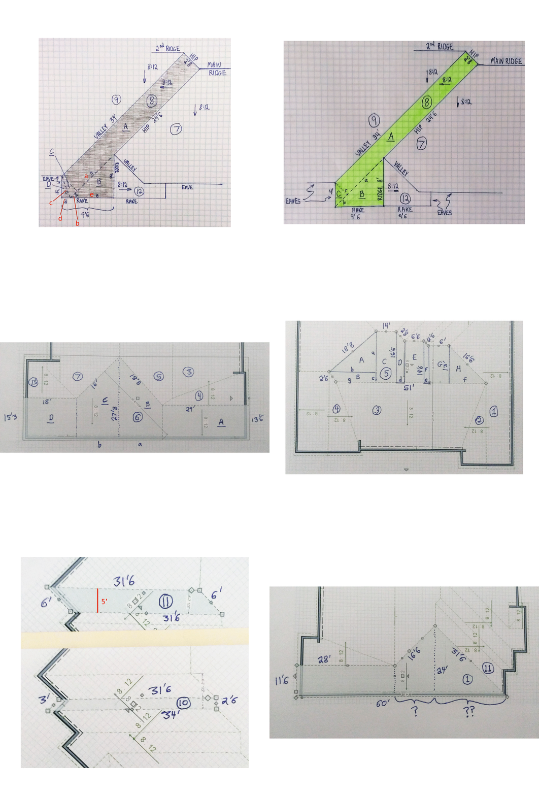
So, to understand how to calculate with perfect precision, here are the principles. We will divide a very complex roof into each component roof plane and calculate for that, then sum up all the planes.
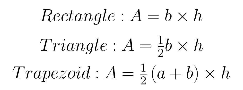
Of course, the math to calculate the area of the plane that is a rectangle, triangle, or trapezoid is pretty straightforward:
Oh yea—and the parallelogram (be careful to note that your ‘height’ is now the perpendicular distance between the two parallel lines).
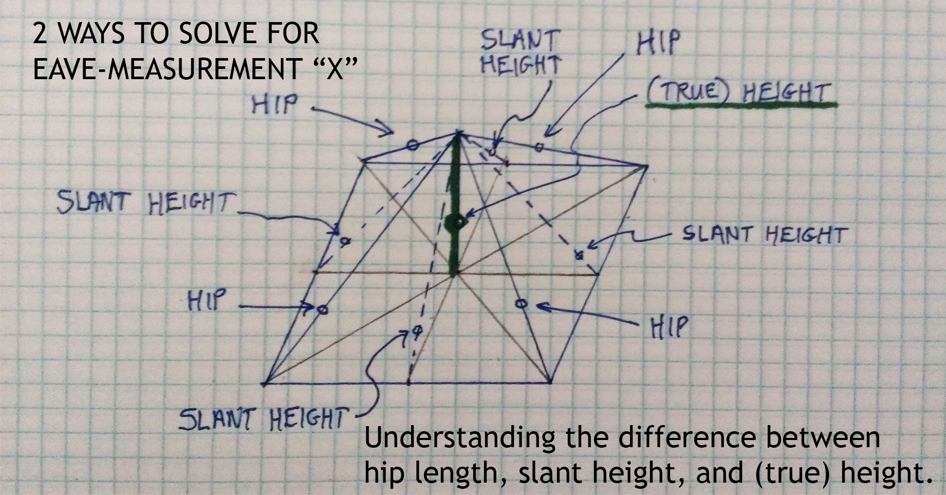
To be clear, the ‘height’ in these equations can’t be directly measured with Google Earth’s ruler—it’s what I like to call a ‘slant height,’ not an absolute height (also not available with the ruler tool). The slant height is the length from the base to the top of a roof plane, if you laid a physical tape measure on it. You could also go in the attic and measure from the ridge straight down to the floor of the attic to get the true or ‘absolute’ height (not relavant here).
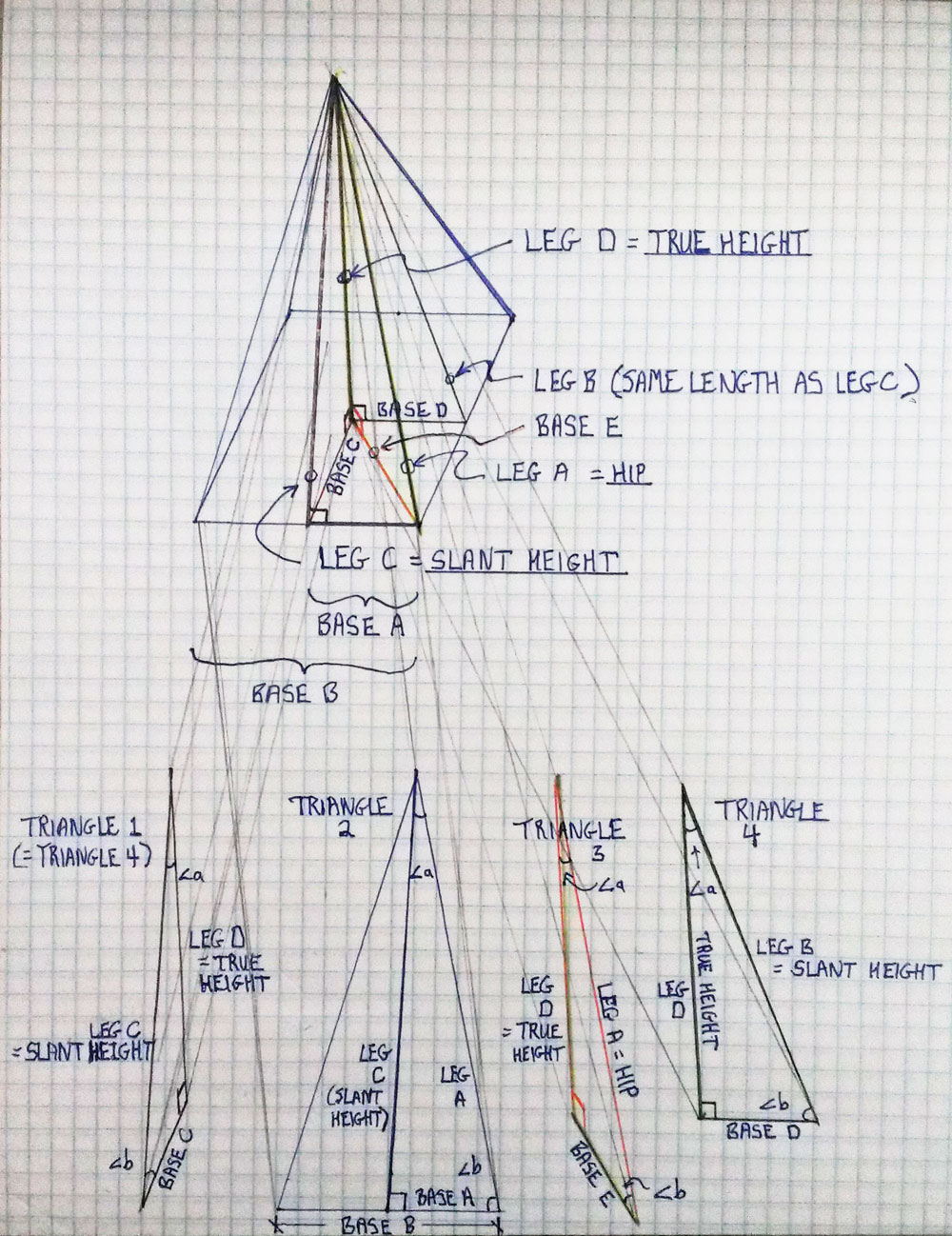
Now, let’s get to something interesting—there are three unique kinds of triangles that are present in a roof, at least abstractly. ‘Triangle 1’ has these three edges: the slant height from the base of the roof to the ridge, a projection of that line onto the attic floor, and vertical line from attic floor to ridge. ‘Triangle 2’ has a slant height edge, a hip edge, and a line that runs along the eave or base of the roof. ‘Triangle 3’ has the hip, its projection along the attic floor underneath, and the vertical line from attic floor to ridge.
I even made a little model and video to elucidate! Note the terms ‘run,’ ‘rise,’ and ‘diagonal’ are Construction Master Pro calculator terms (I’m using ‘rise’ to desribe part of the base of the roof here too). The model is of a ‘pie slice’ cut out of a hip roof to reveal the abstract triangle concepts which can be incredibly useful for obtaining any angle or length.
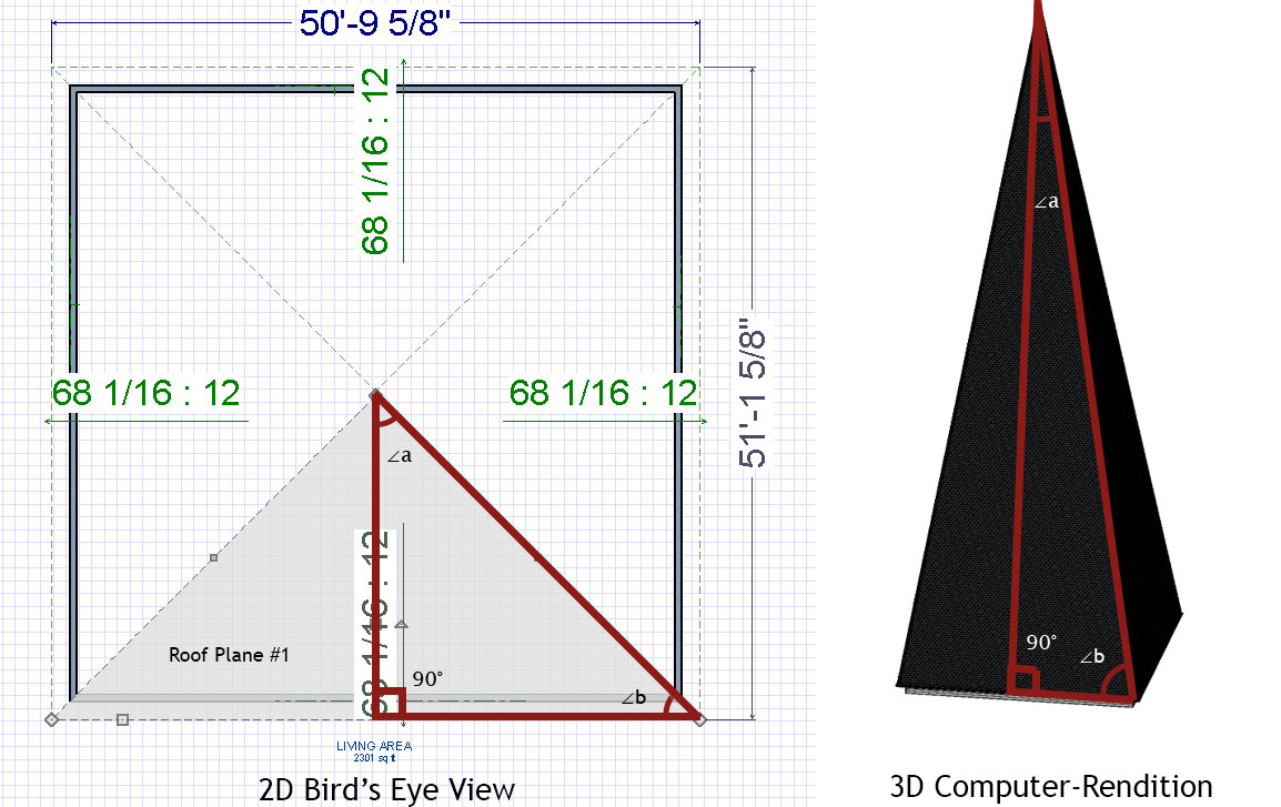
If you are looking at a roof plan, you’ll notice that two angles that appear equal there (a and b) may be very different (extreme example shown below using a very steep roof simulation).
That’s because the plan view can’t convey the full 3D situation—but we know to distinguish these three triangles and their angles now.
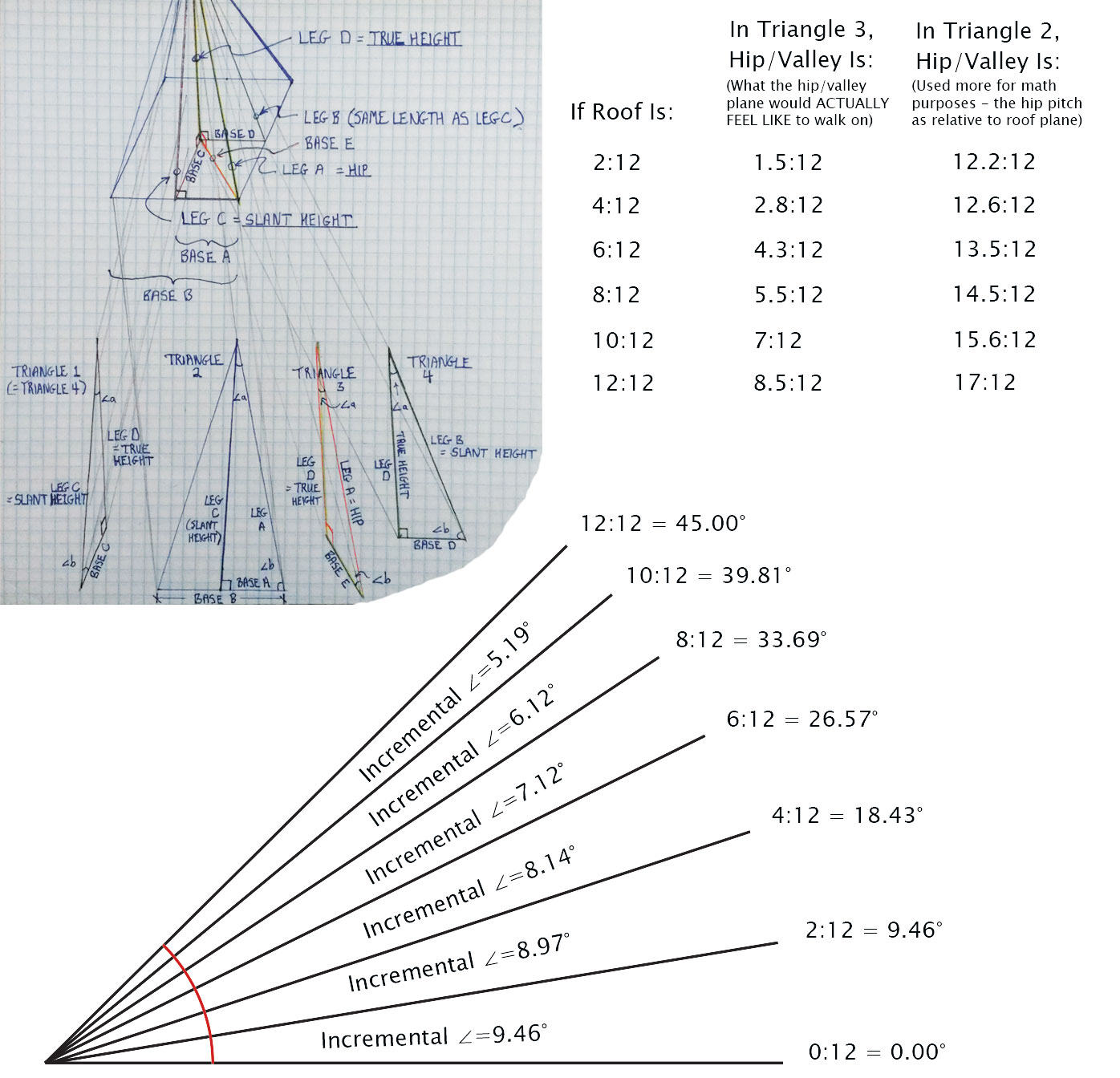
Alright, let’s start crunching numbers so we can utilize geometric constants between these triangles.
Alright, I did the work for ya. Screenshot this table or something—I’ve probably looked it up a hundred times for calculating materials or bidding jobs. I find it invaluable.
Roof Pitch | Slant Height (for a RUN value of 12′) |
*Hip Length (for a RUN value of 12′) |
*Hip Pitch (relative to triangle 2) (relative to eave/transition-run) (Inches : Inches) |
*Hip Pitch (relative to triangle 3) (what it would feel like to walk on) (Inches : Inches) |
---|---|---|---|---|
16:12 | 20′ 0″ | 23′ 3 7/8″ | 20 : 12 | 11 5/16 : 12 |
14:12 | 18′ 5 1/4″ | 22′ 0″ | 18 7/16 : 12 | 9 7/8 : 12 |
12:12 | 16′ 11 5/8″ | 20′ 9 3/8″ | 17 : 12 | 8 1/2 : 12 |
11:12 | 16′ 3 3/8″ | 20′ 2 11/16″ | 16 5/16 : 12 | 7 3/4 : 12 |
10:12 | 15′ 7 7/16″ | 19′ 3 3/8″ | 15 5/8 : 12 | 7 1/16 : 12 |
9:12 | 15′ 0″ | 19′ 2 1/2″ | 15 : 12 | 6 3/8 : 12 |
8:12 | 14′ 5 1/16″ | 18′ 9 1/8″ | 14 7/16 : 12 | 5 11/16 : 12 |
7:12 | 13′ 10 11/16″ | 18′ 4 1/4″ | 13 7/8 : 12 | 4 15/16 : 12 |
6:12 | 13′ 5″ | 18′ 0″ | 13 7/16 : 12 | 4 1/4 : 12 |
5:12 | 13′ 0″ | 17′ 8 5/16″ | 13 : 12 | 3 9/16 : 12 |
4:12 | 12′ 7 13/16″ | 17′ 5 1/4″ | 12 5/8 : 12 | 2 13/16 : 12 |
3:12 | 12′ 4 7/16″ | 17′ 2 13/16″ | 12 3/8 : 12 | 2 1/8 : 12 |
2:12 | 12′ 2″ | 17′ 1 1/16″ | 12 3/16 : 12 | 1 7/16 : 12 |
1:12 | 12′ 0 1/2″ | 17′ 0″ | 12 1/16 : 12 | 0 11/16 : 12 |
As a neat trick, you can also get the slope of a hip/valley (in triangle 3) by taking the first number of the roof slope (say, for an 8:12 roof, take the ‘8’), and divide by 17 instead of 12 (8:17).
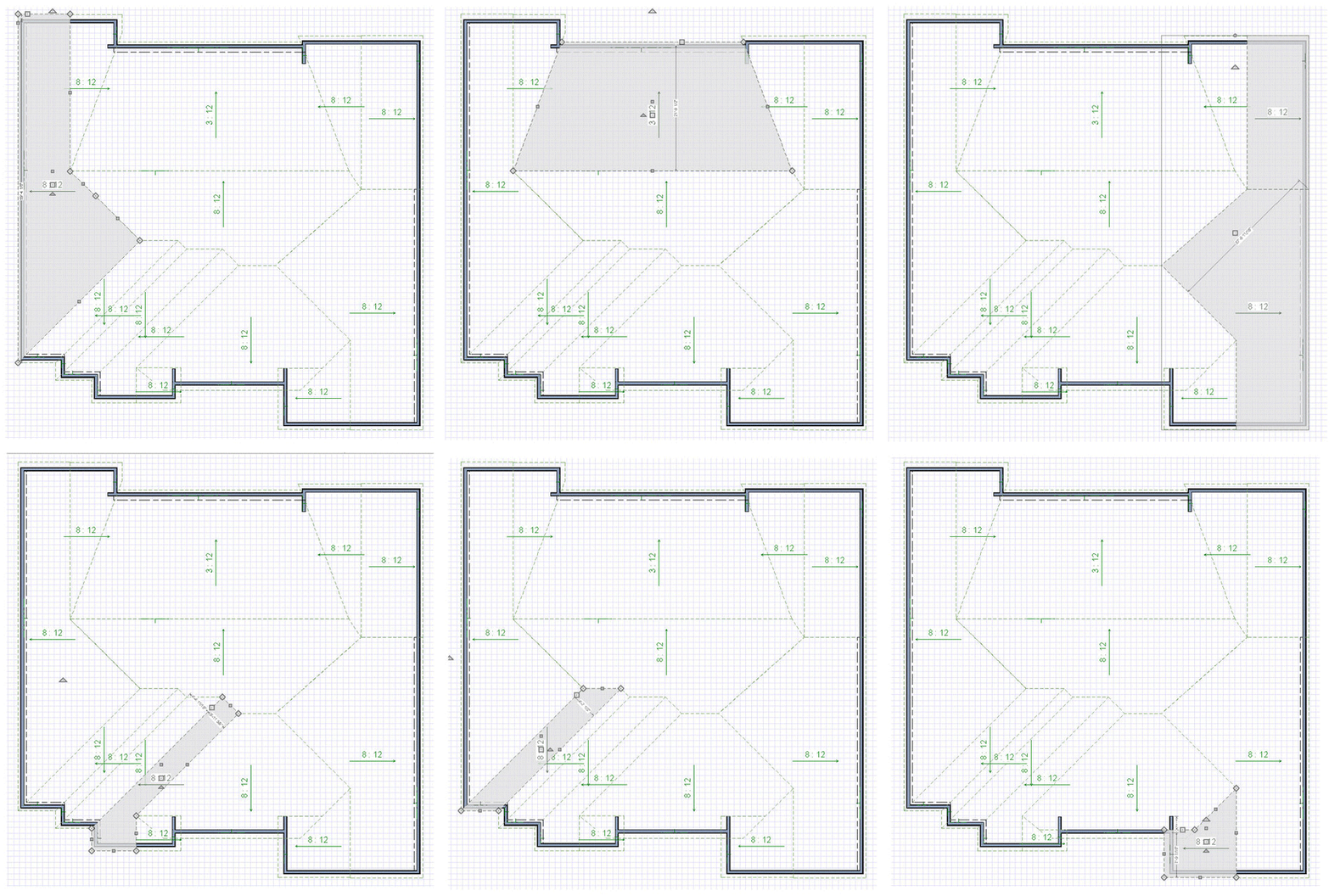
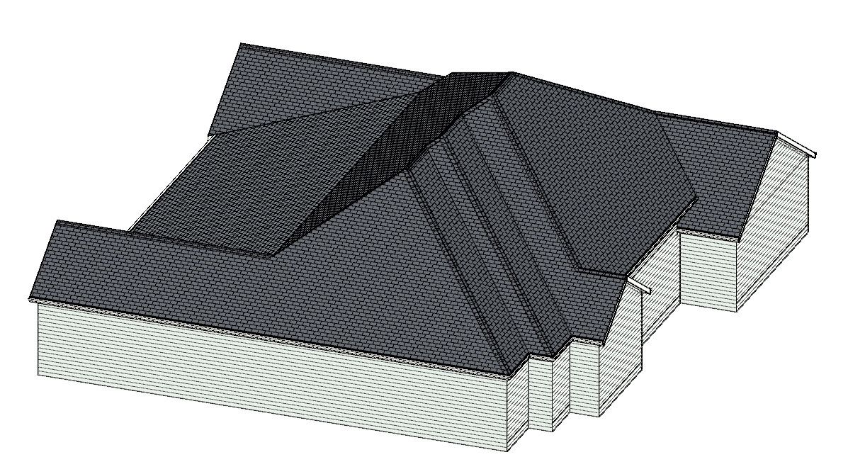
Okay, so let’s measure a roof as an example! Here’s a 3D rendering of it, and the GIF at the start of this article breaks down all the planes.
You can see the process of taking each roof plane and dividing it up into geometric shapes that can calculated. Of course, once you get a hang of it, you can estimate things more quickly and get close enough.
Using these principles, I measured this roof to have a surface area of 5,372 s.f. I also purchased an EagleView plan of this roof, and it came up with 5,376 s.f. (only 4 s.f. different!).
But, this is the ‘geometric skin area’ or ‘surface area’ of the roof surface, and does not include the extra shingles needed for starter, hip/ridge waste, hip/ridge shingles, valley redundancies (overlapping portions), and general waste.
I’ll give you a formula that isn’t perfect, but is pretty good for calculating redundancy in a California-cut style valley. For each course of shingles, coming from one side eats up an extra half shingle (must continue half way past valley midline), and a little more than half on the other side from waste cut and the lay-shingle (stays there as straight line). It does vary a little by roof pitch, but not much, and 3% is easy to remember: valley waste (in squares) is the total length (in feet) along all the valleys times 0.03.
And hip waste is similar but quite a bit less extensive. Each course might lose a fifth of the shingle from each side (2/5th loss per course). So we could figure the length of all the hips in feet times 0.01 (1%) to get hip waste in squares.
There’s also the hip/ridge cap shingles (whether you use cut-up 3-tab or buy the special cap shingles). To figure squares of these is simply the length along all the hips/ridges multiplied by 1′ of width. So the length of hips/ridges is the number of squares needed there.
Somewhat similarly, the linear feet of starter shingles needed is the total length along the eaves and rakes. If you’re flipping 3-tab shingles upside down, multiply by 1′ width and that is the number of squares of starter. If you’re using GAF ProStart, each pack will cover 120 linear feet (consult your own brand for coverage specificity here).
There may be a little waste for shingles that arrive damaged from the factory, or that accidentally fall off the roof, but this is fairly miniscule.
Over time, you get a ‘gut feeling’ of how much waste there is. Often people just add 5-20%, with a roof like that shown here (being very cut up) being closer to the 20% end.
Installing a Galvalume Standing Seam Metal Roof
We installed a shiny galvalume metal roof for this customer. We’ll check out some of the details below.
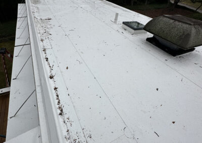
For this type B gas vent, we first installed a heat-resistant orange EPDM boot (with compression mastic fit using screws at 1″ on center around the boot perimeter), then slid a decorative metal shroud over for better aesthetics. You can also see how standing seam panels have a perforated edge for screws that gets covered and hidden by the next panel. Flathead screws are used, and for long panels, it is good to place each screw in the center of its slot to allow a little expansion/contraction of the panel. We also used heat-resistant ice and water shield visible under the panels. This isn’t required for metal at this slope, but was a desired upgrade of the customer.
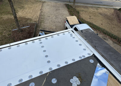
Sidewall flashings are another detail to make sure to do right. We ensure that there is a vertical rib of the panel (white dotted line profile in image), even if we must manually bend it up ourselves using a ‘Wuko bender.’ In the image below, you are at the base of the roof looking upwards (although your first impression might be the opposite!). The flashing (black dotted line profile in image) extends behind the siding, and comes downward over the ‘apron flashing’ at base termination (we bent it at a 45º angle for better aesthetics). All these details are critical to ensure there are no pinpoint spots vulnerable to water leaks. Just remember: water runs downhill!
For the ridge here, we used the z-flashing method (and mastic compression fit between it and the panels where screws went through). Since then, we’ve developed another method using an 8″ x ~1″ x 7″ ‘J-channel’ method that enables us to build the ridge prior to the panel installation using one ridge spanning over two J-channels, all riveted together, and riveted to the panels once they later get slid in. This is a much safer method in our opinion, as it enables installing the most dangerous detail while there is still a non-slick walking surface (prior to panels). A harness or other protection is still required for steep slopes, though.
You can also see that for the rakes (side edges of roof), we used two Wuko benders (one for 0º–90º, the other for 90º–180º, although the second phase can also be bent by hand if using gloves and caution) to bend the entire edge of the panel (yes, the full ~20′) around the drip edge. We also crafted a triangular diverter for the ends of under the ridges (probably not necessary).
A Big Roof Recover Job at Fort Rucker
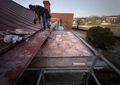
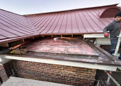
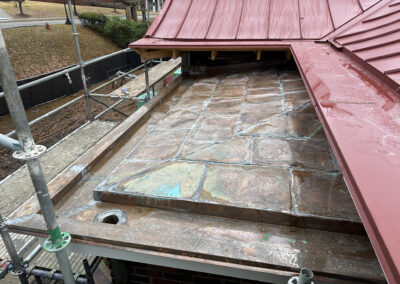
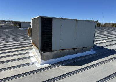
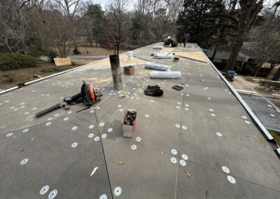
This was a big, tedious job, but I’m proud of it in retrospect. We began with an existing flat and angled combination roof at Fort Rucker (now Fort Novosel) over a gym/daycare building.
Plans spec’d a recover, leaving the angled metal and flat membrane roofs intact while we built a new metal structure on top and then clad the top and sides of it with metal panels.
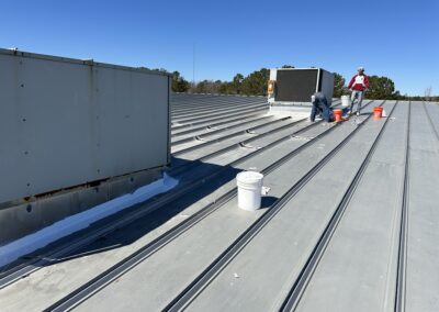
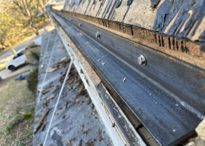
We put mastic under the metal rafters that seated upon the metal roof to mitigate leaks from the fasteners until our new roof was done. Quality mastic in compression like this does a fantastic job of shielding against water leaks.
In the image above, you can see styrofoam thermal spacers we used under the panels. We used spray adhesive glue to attach these styrofoam spacers. Then, floating clips were screwed to the purlins to hold the panels. X-bracing was also used, as seen below.
Find Hip and Ridge Cap Angles for Metal Roofing
This was a rough and quick video, but it shows how to obtain some difficult key angles in metal roofing. To find interior angle of hip caps, the angle needs to be perpendicular to the hip line. Thus, it is slightly different than just using 180°-(2)(hip walk angle). On a flat roof, this is perpendicular. But at other slopes, you need to adjust (for an 8:12 slope, you would need 5 1/8 slope [23.13°] rather than 5 11/16 slope [25.36°]).
36:12 -> 95.74°
12:12 -> 120.02°
10:12 -> 126.17°
8:12 -> 133.69°
6:12 -> 143.00°
4:12 -> 154.62°
2:12 -> 166.14°
36:12 -> 36.87°
12:12 -> 90.00°
10:12 -> 100.39°
8:12 -> 112.62°
6:12 -> 126.87°
4:12 -> 143.13°
2:12 -> 161.08°
1:12 -> 170.47°
36:12 -> 25 7/16 : 12 (64.74°)
12:12 -> 8 1/2 : 12 (35.11°)
10:12 -> 7 1/16 : 12 (30.48°)
8:12 -> 5 11/16 : 12 (25.36°)
6:12 -> 4 1/4 : 12 (19.50°)
4:12 -> 2 13/16 : 12 (13.24°)
2:12 -> 1 7/16 : 12 (6.71°)
1:12 -> 0 11/16 : 12 (3.37°)
36:12 -> 37 15/16 : 12 (72.45°)
12:12 -> 17 : 12 (54.78°)
10:12 -> 15 5/8 : 12 (52.48°)
8:12 -> 14 7/16 : 12 (50.27°)
6:12 -> 13 7/16 : 12 (48.23°)
4:12 -> 12 5/8 : 12 (46.45°)
2:12 -> 12 3/16 : 12 (45.44°)
1:12 -> 12 1/16 : 12 (45.15°)